platforms/boards/pyboard/modpyb/Timer Examples

Pulse Width Modulation (PWM) @ 10 kHz on pins X2 and X3 in center mode
Each timer has a period register which can set either using freq= or prescaler= and period= Each timer can have multiple channels. A channel may be exposed on a pin (sometimes more than one channel (usually from different timers) are exposed on the same pin, but the pin can only choose one).
With PWM, the counter runs from 0..period and the pulse_width detemines how long the pulse stays active. Pin X2 is 25% duty cycle, and X3 is 50% duty cycle.
import pyb

# TIM2 runs at 84 MHz
# at 20000 Hz, count runs from 0 to 4199
# In center mode, the frequency will be halved, so we'll get a 10 kHz output
t2 = pyb.Timer(2, freq=20000, mode=pyb.Timer.CENTER)
ch2 = t2.channel(2, pyb.Timer.PWM, pin=pyb.Pin.board.X2, pulse_width=(t2.period() + 1) // 4)
ch3 = t2.channel(3, pyb.Timer.PWM, pin=pyb.Pin.board.X3, pulse_width=(t2.period() + 1) // 2)
This is what the signal looks like on a logic analyzer:
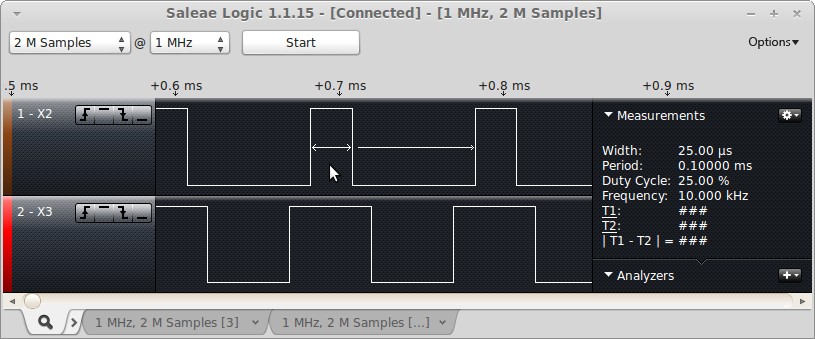
The top channel is set to generate a 25% duty cycle and the bottom is set to generate a 50% duty cycle.
This example is also showing center-aligned PWM, where two channels from the same timer have their PWM pulses aligned in the center. You can edge-align them, although center aligned is better in some cases. It reduces power spikes if you're using the PWM signals to drive motors, for example, when having both edges go active at the same time would produce a larger spike than having them staggered.
PWM performs 2 actions for each "cycle". When the counter reaches zero, it sets the output active (except when the pulse-width is zero), and when the counter reaches the pulse-width value, it sets the output inactive. This is what forms the output pulse.
Output Compare (OC) Mode @ 1 KHz
Pin X2 is OC Mode producing a 1 KHz clock. Pin X3 is PWM at 200 Hz with a 10% duty cycle.
import pyb

# setup oc_clock to be a 1 kHz clock. Since it toggles we want it to toggle
# 2000 times per second to get a 1000 Hz clock.
t2 = pyb.Timer(2, freq=2000)
oc  = t2.channel(2, pyb.Timer.OC_TOGGLE, pin=pyb.Pin.board.X2)

# stup PWM to be 200 Hz with a 1 clock pulse_width
t5 = pyb.Timer(5, prescaler=41999, period=9)
pwm = t5.channel(3, pyb.Timer.PWM, pin=pyb.Pin.board.X3, pulse_width=1)
This is what the signal looks like on a logic analyzer:
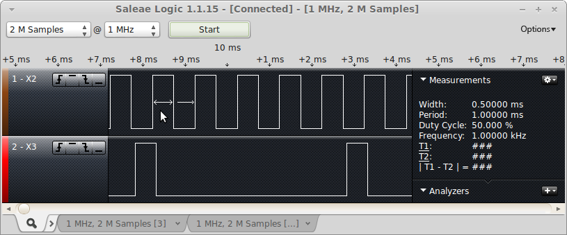
With Output Compare mode, you can only perform one action per cycle. These actions are things like: set-active, set-inactive, toggle. The action occurs when the compare value matches the counter. The example was setup to toggle the output 2000 times per second, which should generate a 1 kHz square wave, which is what the logic analyzer capture shows.
Input Capture (IC) Mode capturing a servo pulse.
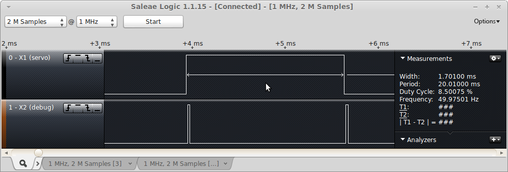
Pin X1 is a servo generated pulse. There is a jumper wire connecting X1 to X4. Pin X2 is a debug pin which is pulsed from within the input capture interrupt routine.
import pyb
import micropython

# This script assumes that there is a jumper wire connecting X1 and X4

# For this example, we'll setup a timer in PWM mode to generate a servo pulse.
# Using a prescalar of 83 gives a timer-tick frequency of 1 MHz (84 MHz / 84).
# The period of 19999 gives a 20,000 usec or 20 msec period. The pulse width
# is then in microseconds.
servo_pin = pyb.Pin.board.X1
t5 = pyb.Timer(5, prescaler=83, period=19999);
servo = t5.channel(1, pyb.Timer.PWM, pin=servo_pin)
servo.pulse_width(1000)

debug_pin = pyb.Pin('X2', pyb.Pin.OUT_PP)

t2 = pyb.Timer(2, prescaler=83, period=0x0fffffff)
ic_pin = pyb.Pin.board.X4
ic = t2.channel(4, pyb.Timer.IC, pin=ic_pin, polarity=pyb.Timer.BOTH)

ic_start = 0
ic_width = 0

def ic_cb(tim):
    global ic_start
    global ic_width
    debug_pin.value(1)
    # Read the GPIO pin to figure out if this was a rising or falling edge
    if ic_pin.value():
        # Rising edge - start of the pulse
        ic_start = ic.capture()
    else:
        # Falling edge - end of the pulse
        ic_width = ic.capture() - ic_start & 0x0fffffff
    debug_pin.value(0)

micropython.alloc_emergency_exception_buf(100)
ic.callback(ic_cb)
pw = 1000
while True:
    servo.pulse_width(pw)
    pyb.delay(200)
    print("pulse_width = %d, ic_width = %d, ic_start = %d" % (pw, ic_width, ic_start))
    pw = ((pw - 900) % 1100) + 1000
This is the output from the REPL:
>>> import ic_test
pulse_width = 1000, ic_width = 1000, ic_start = 179842
pulse_width = 1100, ic_width = 1100, ic_start = 399842
pulse_width = 1200, ic_width = 1200, ic_start = 599842
pulse_width = 1300, ic_width = 1300, ic_start = 799842
pulse_width = 1400, ic_width = 1400, ic_start = 999842
This is the logic analyzer output, zoomed in to show the debug pulses:
This is the logic analyzer output, zoomed out, to show the full servo pulse:
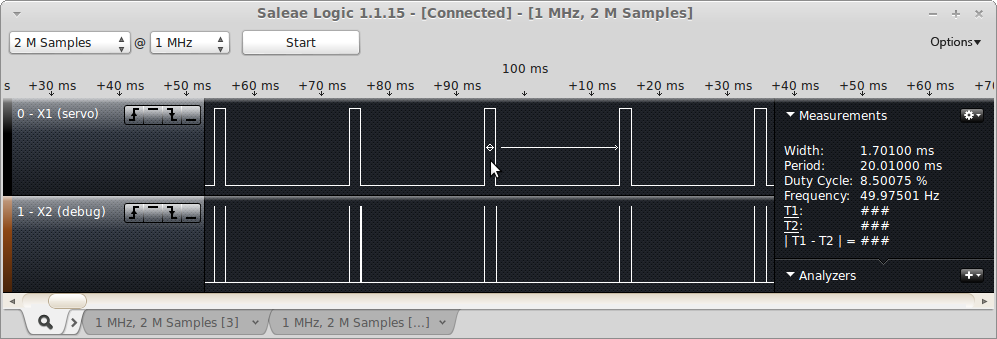
With Input Capture mode, you're configuring the channel to record the value of the counter when some event occurs. You can look for rising edges, falling edges, or both (so 3 different types of events). The third example uses PWM to generate a pulse suitable for driving an RC servo. This is done using timer 5, channel 1, which is sent out on pin X1. It assumes you have a jumper wire connecting X1 and X4 and sets up an input capture on timer 2, channel 4 (which is on pin X4).
The input capture interrupt looks for a rising edge, and when it finds it it saves away the captured value in ic_start. When a falling edge is detected, it subtracts ic_start from the captured value and this then determines the width of the pulse.
5 times per second, the main loop prints out the value of the servo pulse width being generated (in microseonds) and the value of the last captured pulse (also in microseconds). If everything is working properly, they should be the same.