platforms/boards/pyboard/modpyb/Timer Examples

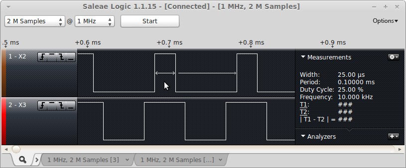
Pulse Width Modulation (PWM) @ 10 kHz on pins X2 and X3 in center mode
Pin X2 is 25% duty cycle, and X3 is 50% duty cycle.
import pyb

# TIM2 runs at 84 MHz
# at 20000 Hz, count runs from 0 to 4199
# In center mode, the frequency will be halved, so we'll get a 10 kHz output
t2 = pyb.Timer(2, freq=20000, mode=pyb.Timer.CtENTER)
ch2 = t2.channel(2, pyb.Timer.PWM, pin=pyb.Pin.board.X2, pulse_width=(t2.period() + 1) // 4)
ch3 = t2.channel(3, pyb.Timer.PWM, pin=pyb.Pin.board.X3, pulse_width=(t2.period() + 1) // 2)
This is what the signal looks like on a logic analyzer:
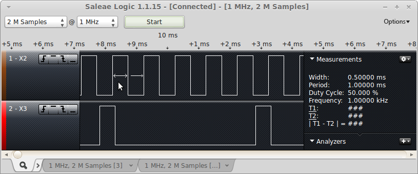
Output Compare (OC) Mode @ 1 KHz
Pin X2 is OC Mode producing a 1 KHz clock. Pin X3 is PWM at 200 Hz with a 10% duty cycle.
import pyb

# setup oc_clock to be a 1 kHz clock. Since it toggles we want it to toggle
# 2000 times per second to get a 1000 Hz clock.
t2 = pyb.Timer(2, freq=2000)
oc  = t2.channel(2, pyb.Timer.OC_TOGGLE, pin=pyb.Pin.board.X2)

# stup PWM to be 200 Hz with a 1 clock pulse_width
t5 = pyb.Timer(5, prescaler=41999, period=9)
pwm = t5.channel(3, pyb.Timer.PWM, pin=pyb.Pin.board.X3, pulse_width=1)
This is what the signal looks like on a logic analyzer:
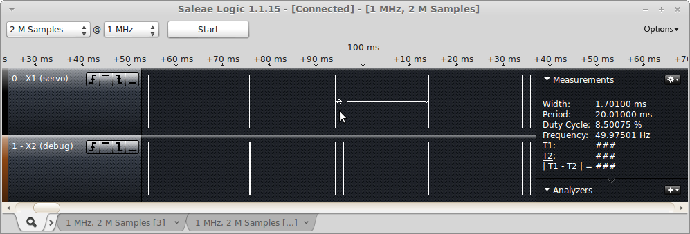
Input Capture (IC) Mode capturing a servo pulse.
Pin X1 is a servo generated pulse. There is a jumper wire connecting X1 to X4. Pin X2 is a debug pin which is pulsed from within the input capture interrupt routine.
import pyb
import micropython

# This script assumes that there is a jumper wire connecting X1 and X4

# For this example, we'll setup a timer in PWM mode to generate a servo pulse.
# Using a prescalar of 83 gives a timer-tick frequency of 1 MHz (84 MHz / 84).
# The period of 19999 gives a 20,000 usec or 20 msec period. The pulse width
# is then in microseconds.
servo_pin = pyb.Pin.board.X1
t5 = pyb.Timer(5, prescaler=83, period=19999);
servo = t5.channel(1, pyb.Timer.PWM, pin=servo_pin)
servo.pulse_width(1000)

debug_pin = pyb.Pin('X2', pyb.Pin.OUT_PP)

t2 = pyb.Timer(2, prescaler=83, period=0x0fffffff)
ic_pin = pyb.Pin.board.X4
ic = t2.channel(4, pyb.Timer.IC, pin=ic_pin, polarity=pyb.Timer.BOTH)

ic_start = 0
ic_width = 0

def ic_cb(tim):
    global ic_start
    global ic_width
    debug_pin.value(1)
    # Read the GPIO pin to figure out if this was a rising or falling edge
    if ic_pin.value():
        # Rising edge - start of the pulse
        ic_start = ic.capture()
    else:
        # Falling edge - end of the pulse
        ic_width = ic.capture() - ic_start & 0x0fffffff
    debug_pin.value(0)

micropython.alloc_emergency_exception_buf(100)
ic.callback(ic_cb)
pw = 1000
while True:
    servo.pulse_width(pw)
    pyb.delay(200)
    print("pulse_width = %d, ic_width = %d, ic_start = %d" % (pw, ic_width, ic_start))
    pw = ((pw - 900) % 1100) + 1000
This is the output from the REPL:
>>> import ic_test
pulse_width = 1000, ic_width = 1000, ic_start = 179842
pulse_width = 1100, ic_width = 1100, ic_start = 399842
pulse_width = 1200, ic_width = 1200, ic_start = 599842
pulse_width = 1300, ic_width = 1300, ic_start = 799842
pulse_width = 1400, ic_width = 1400, ic_start = 999842
This is the logic analyzer output, zoomed in to show the debug pulses:
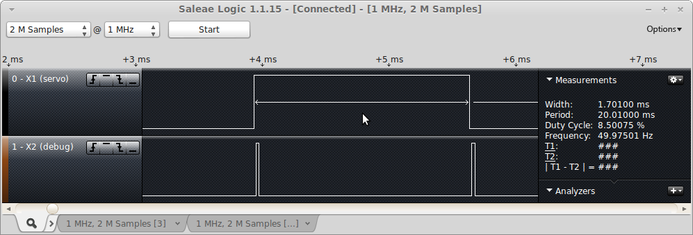
This is the logic analyzer output, zoomed out, to show the full servo pulse: